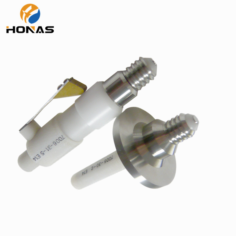
E14/E27 gauge
E14 cap Gauge
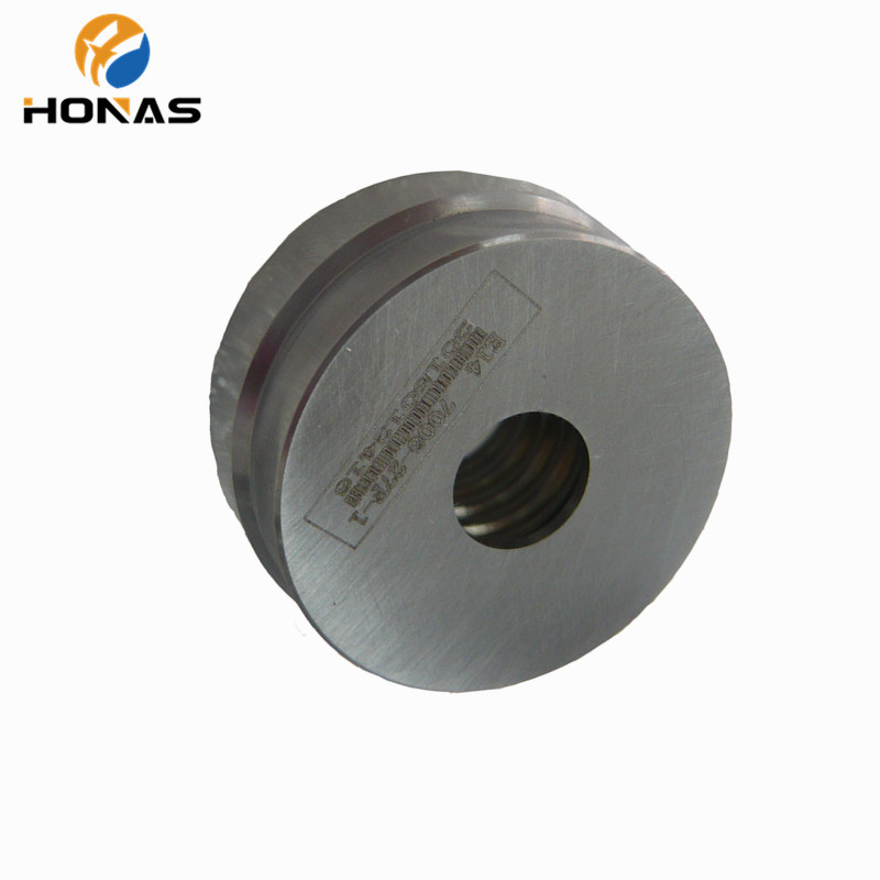
- 1.Go (IEC 7006-27F-1)
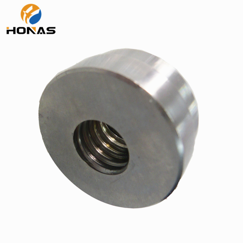
- 2.Not go (IEC 7006-28B-1)
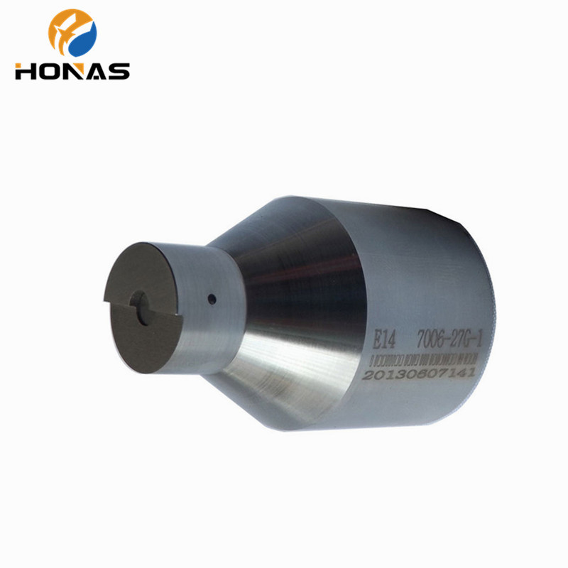
- 3.Go for S1 dimension gauge (IEC 7006-27G-1)
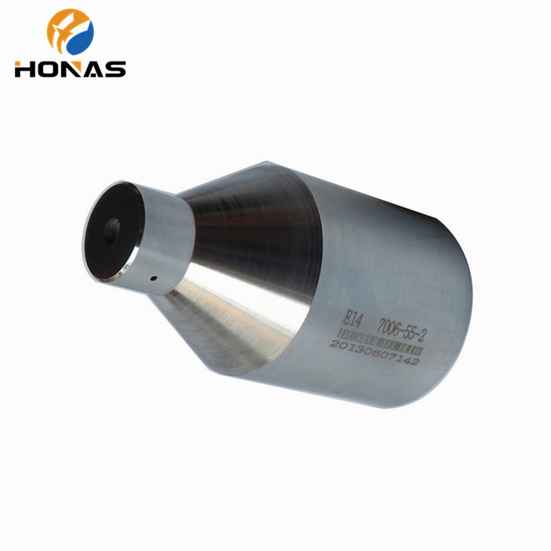
- 4.Contact-making gauge (IEC 7006-54-2)
- Product description:E14 cap Gauge
1. Go (IEC 7006-27F-1)
|
Reference |
Dimension(mm) |
Tolerance(mm) |
Limit after wear (mm) |
|
P |
2.822 |
- |
|
|
T |
16.0 |
+0.0/-0.03 |
|
|
d |
13.89 |
+0.03/-0 |
13.93 |
|
d1 |
12.29 |
+0.03/-0 |
12.33 |
|
L |
9.5 |
±0.1 |
|
|
O |
15 |
±0.2 |
|
|
r |
0.822 |
- |
|
|
V |
12.5 |
±0.1 |
|
|
W |
2 |
±0.1 |
|
The shape part of the edge of the thread shall be broken with radius of 0.2mm to 0.3mm.
Purpose:
To check the maximum dimensions of the screw thread and dimension T1 minimum of caps on finished lamps.
Testing :
When the cap on a finished lamp has been screwed into the gauge as far as it will go, the center contact shall be co-planar with, or project beyond, surface X.
2. Not go (IEC 7006-28B-1)
|
Reference |
Dimension(mm) |
Tolerance(mm) |
|
L |
9.5 |
±0.1 |
|
U |
1 |
+0.0/-0.1 |
|
V |
12.0 |
+0.05/-0 |
|
W |
1.5 |
±0.1 |
|
d |
13.6 |
+0.0/-0.01 |
|
α |
Nom. 45° |
|
|
Weight |
0.1kg |
±10% |
Purpose:
To check the minimum outside (major) diameter of the screw thread.
Testing :
When the gauge is placed over the thread of the cap on a finished lamp, held cap uppermost, the center contact shall not project beyond surface “X”. Only the weight of the gauge itself shall be used in the test.
3. Go for S1 dimension gauge (IEC 7006-27G-1)
|
Reference |
Dimension(mm) |
Tolerance(mm) |
|
O |
12 |
±0.03 |
|
S |
4.5 |
+0.01/-0.0 |
|
V |
1 |
+0.02/-0.0 |
|
d |
13.94 |
+0.03/-0.0 |
|
h |
7.5 |
±0.1 |
|
m |
11 |
±0.1 |
Purpose:
To check the dimensions S1 minimum and S1 maximum of E14 caps on finished lamps.
Testing :
When the cap on a finished lamp has been pushed into the gauge as far as it will go, the plunger surface “W” shall be co-planar with or project beyond surface “X” but it shall not project beyond surface “Y”.
4. Contact-making gauge (IEC 7006-54-2)
The gauge is shown in the test position. In the rest position the plunger shall be above plane V.
|
Reference |
Dimension(mm) |
Tolerance(mm) |
Reference |
Dimension(mm) |
Tolerance(mm) |
|
D |
13.97 |
+0.0/-0.02 |
M |
20.02 |
+0.02/-0.0 |
|
G |
22 |
+0.0/-0.02 |
N |
27.15 |
+0.02/-0.0 |
|
H |
7.5 |
±0.1 |
O |
30.65 |
+0.01/-0.0 |
|
J |
29 |
+0.0/-0.02 |
T |
16 |
+0.03/-0.0 |
Purpose:
To check lamp dimensions for contact making in IEC holders.
Testing :
The shape of the lamp with regard to the fit in the lampholder is assured to be correct. If the lamp can be pushed into the gauge till plane W reaches plane V or project beyond it. The application of this gauge is restricted to the following lamps when they are fitted with E14 caps, in accordance with sheet 7004-23: candle lamps/round bulb lamps/domestic tubular lamps/pygmy lamps.
5. Protection against accidental contact during insertion (IEC 7006-55-2)
The gauge is shown in the test position. In the rest position, the plunger shall be above plane V.
|
Reference |
Dimension(mm) |
Tolerance(mm) |
Reference |
Dimension(mm) |
Tolerance(mm) |
|
D |
13.97 |
+0.0/-0.02 |
Q |
15 |
±0.1 |
|
F |
18.1 |
+0.05/-0.0 |
R |
Approx. 12.5 |
|
|
G |
19 |
+0.02/-0.0 |
U |
8 |
±0.1 |
|
H |
7.5 |
±0.1 |
r |
<0.5 |
|
|
M |
27.5 |
±0.1 |
r1 |
2.5 |
+0.5/-0.0 |
|
N |
28.5 |
+0.0/-0.02 |
α |
35° |
±30’ |
|
P |
10 |
±0.1 |
|
|
|
Purpose:
To check protection against accidental contact during insertion of caps E14 on finished lamps.
Testing :
The shape of the lamp with regard to protection against accidental contact is assumed to be correct if, when the lamp is pushed as far as possible into the gauge, surface W does not protrude beyond surface V. The application of this gauge is restricted to the following lamps when they are fitted with E14 caps, in accordance with sheet 7004-23: candle lamps/round bulb lamps/domestic tubular lamps/pygmy lamps.
Categories
Contact
CONTACT USContact:Anna
Phone: +86 14775548318
Email: hns@szhonas.com
Whatsapp: +86-14775548318
Add:805 Jingfa Building, No. 46 Baoqian Lane, Baoqian Road, Baoan District, Shenzhen
 Anna
Anna SZ HONAS
 +86-14775548318